
Murata posted news in the website that trimmer capacitors will be discontinued after 2021 March. As a competitor, we suppose that TZR1 Series (Ultra-small and thin with external dimensions of 1.5(W)x1.7(L)x0.85(H)mm) and TZW4 Series (Compact size: 4.2(W)x5.2(L)x2.6max.(H)mm) have no replacement product in the market for the same capacitance and size.
Could you please think about using Kingtornics ceramic trimmer capacitors KKT series small size with external dimension of 3.2(W) x 4.5(L) x 1.5(T) mm? Unique construction with no plastic material provides superior soldering heat resistance to maintain excellent characteristic performance after reflow soldering. It is suitable for high frequency circuit due to high self-resonant.
| Company | Capacitance (pF MAX) | Part Number | L x W (size) | Status |
| Kingtronics | 3pF | KKT-303TR (Black) | 3.2(W) x 4.5(L) x 1.5(T) mm | hot selling |
| 6pF | KKT-306TR (Blue) | 3.2(W) x 4.5(L) x 1.5(T) mm | hot selling | |
| 10pF | KKT-310TR (Ivory) | 3.2(W) x 4.5(L) x 1.5(T) mm | hot selling | |
| 20pF | KKT-320TR (Pink) | 3.2(W) x 4.5(L) x 1.5(T) mm | hot selling | |
| 30pF | KKT-330TR (Green) | 3.2(W) x 4.5(L) x 1.5(T) mm | hot selling | |
| Murata | 8pF | TZR1R080A001B00 | 1.5(W)x1.7(L)x0.85(H)mm | To be discontinued |
| 8pF | TZR1R080A001R00 | 1.5(W)x1.7(L)x0.85(H)mm | To be discontinued | |
| 1pF | TZR1Z010A001B00 | 1.5(W)x1.7(L)x0.85(H)mm | To be discontinued | |
| 1pF | TZR1Z010A001R00 | 1.5(W)x1.7(L)x0.85(H)mm | To be discontinued | |
| 4pF | TZR1Z040A001B00 | 1.5(W)x1.7(L)x0.85(H)mm | To be discontinued | |
| 4pF | TZR1Z040A001R00 | 1.5(W)x1.7(L)x0.85(H)mm | To be discontinued | |
| 1.5pF | TZR1Z1R5A001B00 | 1.5(W)x1.7(L)x0.85(H)mm | To be discontinued | |
| 1.5pF | TZR1Z1R5A001R00 | 1.5(W)x1.7(L)x0.85(H)mm | To be discontinued | |
| 1pF | TZW4Z010A001B00 | 4.2(W)x5.2(L)x2.6max.(H)mm | To be discontinued | |
| 1pF | TZW4Z010A001R00 | 4.2(W)x5.2(L)x2.6max.(H)mm | To be discontinued | |
| 1.5pF | TZW4Z1R5A001B00 | 4.2(W)x5.2(L)x2.6max.(H)mm | To be discontinued | |
| 1.5pF | TZW4Z1R5A001R00 | 4.2(W)x5.2(L)x2.6max.(H)mm | To be discontinued |
Note:The product information in this catalog is for reference only,Please contact our sales before ordering: info@kingtronics.com

In response to environmental protection, we provide nylon folding reusable bags. Feel free to let us ship with your goods or samples shipments.
More free promotion materials can be prepared: http://www.kingtronics.com/packing/Kingtronics-Promotion-Materials.html
Let us know if more support is needed. Look forward to more prosperity in 2019.
Stock:
Full Range Catalog
M7, SM4007,LL4148, BZV55C Leaflet
Aluminum Elec. Capacitors & Bridge Rectifier Leaflet
Transistors and Diodes Leaflet
Paper Sample Box
PCB Sample Box
E-Cap File Folder Souvenir
M7 File Folder Souvenir
e-catalogues:
Aluminum Elec. Capacitors Leaflet
3MM Ceramic Capacitors Leaflet
Dip and SMD Tact Switch Leaflet

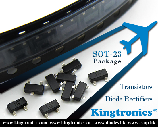
Kt Kingtronics SOT-23 Package Diodes and Transistors Support is Resumed Normal & even Better
1 Feb 2019In second half of 2018, we met tough challenge with SOT-23 package diodes and transistors raw material supplies.
The prices increased and lead time was much longer than ever before.
Fortunately, SOT-23 package support is resumed normal in late Jan, 2019.
We even have chance to offer better prices than the original ones for some values with big quantity now.
Welcome to share request to check our latest support !
Ceramic Trimmer capacitors are variable capacitors. They are mounted directly on the PCB board with a provision to vary their value using a small screwdriver.The trimmer capacitors are serving the purpose of initial calibration of equipment during manufacturing or servicing and are not meant to be varied by the end user. It is used to remote keyless entry system, measuring instrument, security system and wireless microphone.
Murata Ceramic Trimmer Capacitors TZB4 and TZC3 series to be discontinued in 2019. As a competitor, Kingtronics KKT series can replace Murata TZC3 series. If you are looking for a TZB4 series ,we recommend that you change the devices size to fit KKT series because of there is no direct replacrment product in competitors.
Kingtronics KKT SMD 3mm Chip Ceramic Trimmer Capacitor Features:
1)Small size with external dimension of 3.2(W) x 4.5(L) x 1.5(T) mm.
2) Color coded case permits easy identification.
3) Heat resistant resin withstands reflow soldering temperatures.
4)Bulk and reel packaging are available.
Kingtronics corresponds to Murata products as follows:
| Capacitance (pF MAX) | Kingtronics | Murata |
| Part Number | Part Number | |
| 3pF | KKT-303TR(Black) | TZC3Z030A110R00(Brown) |
| TZC3Z030A110B00(Brown) | ||
| N/A | TZC3Z030AA01R00(Black) | |
| TZC3Z030AA01B00(Black) | ||
| 6pF | KKT-306TR (Blue) | TZC3Z060A110R00(Blue) |
| TZC3Z060A110B00(Blue) | ||
| N/A | TZC3Z060AA01B00(Black) | |
| TZC3Z060AA01R00(Black) | ||
| 10pF | KKT-310TR (Ivory) | TZC3R100A110R00(White) |
| TZC3R100A110B00(White) | ||
| N/A | TZC3R100AA01B00(Black) | |
| TZC3R100AA01R00(Black) | ||
| 20pF | KKT-320TR (Pink) | TZC3P200A110R00(Red) |
| TZC3P200A110B00(Red) | ||
| N/A | TZC3P200AA01R00(Black) | |
| TZC3P200AA01B00(Black) | ||
| 30pF | KKT-330TR (Green) | TZC3P300A110R00(Green) |
| TZC3P300A110B00(Green) | ||
| N/A | TZC3P300AA01B00(Black) | |
| TZC3P300AA01R00(Black) |

As you know every year approaching the Christmas season will get busy with factories, so does Chinese New Year time.
The coming Chinese New Year also known as Lunar New Year or Spring Festival.
This is a time for family reunion, and is considered the most important part in the Chinese New Year celebration.
In 2019, the festivity will be on 5th-7th Feb., our factory will have holidays from late January till mid-February.
The production lead time might be longer once place order within or after CNY.
Thus please don’t hesitate to advise us the order confirmation soon, and arrange production without delay. : )
Good day !
More detail:http://kingtronics.com/

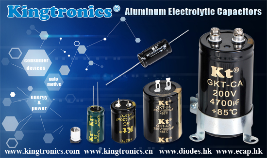
The research has shown, “The aluminum electrolytic capacitor market is projected to grow at a CAGR of 2.05% to reach US$6.894 billion by 2023, from US$6.105 billion in 2017.”
Nowadays, people strives for more conveniences and better innovations in new technology.
Behind the scenes, do you know Aluminum Electrolytic Capacitor plays an important role in our daily life?
Across a wide variety of industries, it could be counted as the most widely used capacitors.
Applications such as the fast-growing market of automotive, highly-demanded consumer devices, energy and power, etc.
Kingtronics offers fine quality for Aluminum Electrolytic Capacitor, and is able to support with an urgent 5-9 weeks lead time.
Official website: http://www.ecap.hk/
For inquiries, please don’t hesitate to contact: info@kingtronics.com
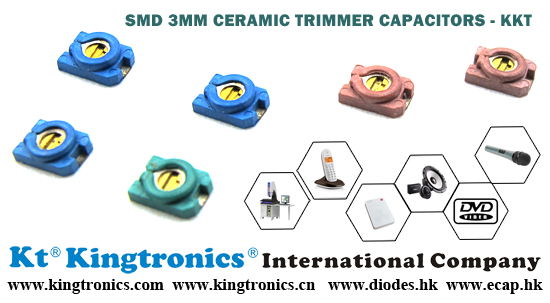
Kt Kingtronics Backs You up When the Foreseeable Shortage of Trimmer Capacitors in Global Market
8 Jan 2019Have you had the latest news that MuRata will stop offer Ceramic Trimmer Capacitor TZC3 series after 2019 March?
Do not worry! Kingtronics can be your best support for KKT series with regular stock, competitive price, RoHS qualification!
Contact us directly if you want to know more.
Datasheet: http://www.kingtronics.com/pdf/KKT-SMD-3mm-Ceramic-Trimmer-Capacitor.pdf
Video: https://youtu.be/Men9BCDlODk
| Kingtronics P/N | Murata P/N | Capacitance |
| KKT303TR | TZC3Z030 | 3pF |
| KKT306TR | TZC3Z060 | 6pF |
| KKT310TR | TZC3Z100 | 10pF |
| KKT320TR | TZC3Z200 | 20pF |
| KKT330TR | TZC3Z300 | 30pF |
Application:
remote keyless entry system, measuring instrument
car alarm remote controller, car audio, traffic card reader
security system, wireless microphone,cordless phone, wireless repeater
two-way radial communication(FRS, GMRS, LMR),TCXO, VCXO, RF module, RFID, DVD
TV, VCD, radio, DVD, telephone, office automation equipment, various remote control and information communication equipment
Compact radio, stereophone, Pager, Portable radio, Hybrid integrated circuit, Cellular phone, Cordless telephone, Remote keyless entry
Through years efforts, we have been working on not only best quality but also competitive offer for our valued customers~
Below you can find our faster lead time in global electronic market for our Trimmers. Feel free to have a try !
Please let us know if there is any scope to work together in coming New Year !
Learn more:http://kingtronics.com/trimming-potentiometers/

A. Because the capacity of electrolytic capacitors is much larger than that of general fixed capacitors, the appropriate range should be selected for different capacities when measuring. In general, the capacitance between 1 ~ 47μF can be measured by R × 1k, and larger than 47μF can be measured by R × 100.
A、因為電解電容的容量較一般固定電容大得多,所以,測量時,應針對不同容量選用合適的量程。一般情況下,1~47μF間的電容,可用R×1k擋測量,大於47μF的電容可用R×100擋測量。
B. Connect the red meter to the negative pole and the black meter to the positive pole. At the moment of contacting, the pointer deflects to the right largely (for the same resistance, the larger the capacity, the larger the swing), and then gradually turn left until it stops at a certain point, which is the forward leakage resistance that is slightly larger than the reverse leakage resistance. The leakage resistance should generally be above hundreds kΩ, otherwise, it will not work properly. In the test, if there is no charging phenomenon in the forward direction and the reverse direction, that is the needle does not move, which means that the capacity disappears or the internal circuit is broken. If the resistance measured is small or zero, it indicates that the capacitor is large leakage resistance or has been broken and damaged, cannot be use any more.
B、將萬用表紅表筆接負極,黑表筆接正極,在剛接觸的瞬間,萬用表指針即向右偏轉較大偏度(對於同一電阻擋,容量越大,擺幅越大),接着逐漸向左迴轉,直到停在某一位置。此時的阻值便是電解電容的正向漏電阻,此值略大於反向漏電阻。電解電容的漏電阻一般應在幾百kΩ以上,否則,將不能正常工作。在測試中,若正向、反向均無充電的現象,即錶針不動,則說明容量消失或內部斷路;如果所測阻值很小或為零,說明電容漏電大或已擊穿損壞,不能再使用。
C. For the electrolytic capacitor whose signs are unknown, it can be discriminated by using the above method. Frist, measure the leakage resistance at randomly and remember its swing. Then, exchange the test leads to measure a resistance. In two measurements, the large resistance is the forward connection, that is the black meter is connected to the positive pole and the red one is connected to the negative pole.
C、對於正、負極標誌不明的電解電容器,可利用上述測量漏電阻的方法加以判別。即先任意測一下漏電阻,記住其大小,然後交換表筆再測出一個阻值。兩次測量中阻值大的那一次便是正向接法,即黑表筆接的是正極,紅表筆接的是負極。
D. Via the multimeter to charge the electrolytic capacitor from the positive and the reverse side, the capacity can be estimated according to the magnitude of the swinging.
D、使用萬用表電阻擋,採用給電解電容進行正、反向充電的方法,根據指針向右擺動幅度的大小,可估測出電解電容的容量。
Additional information about Kingtronics can be found at http://kingtronics.com/

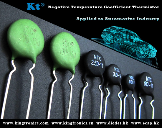
What leads Thermistors to failure mode (short circuit mode and open-circuit mode)?
The reason why substrate burn-down and blow off occurred while turning on devices, subjected to low temperature of sintering, ceramic isn’t firing mature, as well as mechanical stressed, causing larger current than the ripple current can tolerate, etc …
Solutions:
1) Sintering at the right temperature.
2) Reduce defects
3) Avoid large current
4) Only use high purity, and good raw materials
The demand for Negative Temperature Coefficient Thermistor has been increased these years in automotive industry, for the use of powertrain, safety and controls, as well as in alternative of fuel vehicles, since the awareness of eco-friendly has arouse.
Thermistors are growing steady in the market at the moment.
And also, the research has shown that this trend will keep following up in the upcoming years.
For more info about our offer, please contact: info@kingtronics.com
Contact us
Tel: (86) 769 8118 8110
Tel: (852) 8106 7033
Fax: (852) 8106 7099
E-mail: info@kingtronics.com
Microsoft Teams: Kingtronics.sales via Teams
WhatsApp: Chat with us on WhatsApp
Web: www.Kingtronics.com
YouTube: www.youtube.com/c/Kingtronicskt
About
Kingtronics International Company was established in 1995 located in Dongguan City of China to handle all sales & marketing for factories located in Chengdu, Sichuan and Zhaoqing, Guangdong, China. In 1990, we established the first factory to produce trimming potentiometer and in 1999 we built up new factory in Zhao Qing, Guangdong. Now with around 850 workers, Kingtronics produce trimming potentiometers, dipped tantalum capacitors, multilayer ceramic capacitors, and diode & bridge rectifier. We sell good quality under our brand Kingtronics, and Kt, King, Kingtronics are our three trademarks. All our products are RoHS compliant, and our bridge rectifier have UL approval. Please visit our Products page, you could please download all our PDF datasheet and find cross reference for our Trimming Potentiometer and capacitors.
Tantalum and Ceramic Capacitors Cross Reference ↓ Download
Diodes & Rectifiers List(PDF: 97KB) ↓ Download
Trimming Potentiometer Cross Reference ↓Download
Categories
 Kt Kingtronics (252)
- Aluminum Electrolytic Capacitor (165)
- Diodes & Rectifiers (162)
- Trimming Potentiometers (130)
- Tantalum Capacitors (96)
- Multilayer Ceramic Capacitors (70)
- Kt Bridge Rectifier (66)
- Quartz Crystals (65)
- Film Capacitors (44)
- Surge Arresters (34)
- Tactile Switches (34)
- Kt Kingtronics Components (31)
- Ceramic Trimmer Capacitors (27)
- Super Capacitors (22)
- Metal Oxide Varistor (13)
- Negative Temperature Coefficient Thermistor (6)
- Special Purpose Film Capacitors (3)
- Music capacitors (2)
- Conduction Cooled Capacitors (1)
- Audio Capacitors (1)
- Resistors (2)
- LED Display Modules (1)
Archives
- 2026 June (1)
- 2026 May (2)
- 2026 April (1)
- 2026 March (1)
- 2026 February (2)
- 2026 January (2)
- 2025 December (3)
- 2025 November (2)
- 2025 October (2)
- 2025 September (4)
- 2025 August (4)
- 2025 July (4)
- 2025 June (6)
- 2025 May (4)
- 2025 April (3)
- 2025 March (3)
- 2025 February (3)
- 2025 January (4)
- 2024 December (2)
- 2024 November (5)
- 2024 October (4)
- 2024 September (6)
- 2024 August (9)
- 2024 July (6)
- 2024 June (5)
- 2024 May (3)
- 2024 April (3)
- 2024 March (2)
- 2024 February (2)
- 2024 January (3)
- 2023 December (1)
- 2023 November (2)
- 2023 October (1)
- 2023 September (2)
- 2023 August (2)
- 2023 July (4)
- 2023 June (12)
- 2023 May (6)
- 2023 April (4)
- 2023 March (3)
- 2023 February (2)
- 2023 January (1)
- 2022 December (3)
- 2022 November (2)
- 2022 October (3)
- 2022 September (4)
- 2022 August (3)
- 2022 July (3)
- 2022 June (2)
- 2022 May (3)
- 2022 April (4)
- 2022 March (4)
- 2022 February (2)
- 2022 January (3)
- 2021 December (4)
- 2021 November (3)
- 2021 October (4)
- 2021 September (4)
- 2021 August (4)
- 2021 July (4)
- 2021 June (5)
- 2021 May (4)
- 2021 April (3)
- 2021 March (4)
- 2021 February (4)
- 2021 January (4)
- 2020 December (5)
- 2020 November (4)
- 2020 October (4)
- 2020 September (7)
- 2020 August (8)
- 2020 July (9)
- 2020 June (8)
- 2020 May (9)
- 2020 April (11)
- 2020 March (6)
- 2020 February (4)
- 2020 January (4)
- 2019 December (6)
- 2019 November (7)
- 2019 October (6)
- 2019 September (5)
- 2019 August (9)
- 2019 July (6)
- 2019 June (4)
- 2019 May (16)
- 2019 April (6)
- 2019 March (6)
- 2019 February (9)
- 2019 January (5)
- 2018 December (4)
- 2018 November (4)
- 2018 October (5)
- 2018 September (8)
- 2018 August (10)
- 2018 July (7)
- 2018 June (12)
- 2018 May (22)
- 2018 April (4)
- 2018 March (4)
- 2018 February (8)
- 2018 January (13)
- 2017 December (4)
- 2017 November (4)
- 2017 October (5)
- 2017 September (4)
- 2017 August (20)
- 2017 July (7)
- 2017 June (5)
- 2017 May (4)
- 2017 April (4)
- 2017 March (8)
- 2017 February (8)
- 2017 January (8)
- 2016 December (10)
- 2016 November (16)
- 2016 October (8)
- 2016 September (10)
- 2016 August (13)
- 2016 July (12)
- 2016 June (10)
- 2016 May (14)
- 2016 April (8)
- 2016 March (10)
- 2016 February (6)
- 2016 January (8)
- 2015 December (10)
- 2015 November (8)
- 2015 October (3)
- 2015 July (5)
- 2015 June (9)
- 2015 May (7)
- 2015 April (8)
- 2015 March (9)
- 2015 February (7)
- 2015 January (5)
- 2014 December (13)
- 2014 November (4)
- 2014 October (4)
- 2014 September (5)
- 2014 August (4)
- 2014 July (4)
- 2014 June (4)
- 2014 May (4)
- 2014 April (4)
- 2014 March (5)
- 2014 February (3)
- 2014 January (4)
- 2013 December (8)
- 2013 November (9)
- 2013 October (10)
- 2013 September (9)
- 2013 August (11)
- 2013 July (10)
- 2013 June (3)
- 2013 May (4)
- 2013 April (3)
- 2013 March (2)
- 2013 February (1)
- 2013 January (3)
- 2012 December (5)
- 2012 November (6)
- 2012 October (5)
- 2012 September (10)
- 2012 August (11)
- 2012 July (11)
- 2012 June (12)
- 2012 May (14)
- 2012 April (9)
- 2012 March (14)
- 2012 February (9)
- 2012 January (6)
- 2011 December (9)
- 2011 November (11)
- 2011 October (10)
- 2011 September (13)
- 2011 August (14)
- 2011 July (13)
- 2011 June (13)
- 2011 May (13)
- 2011 April (14)
- 2011 March (27)
- 2011 February (13)
- 2011 January (24)
- 2010 December (21)
- 2010 November (12)
- 2010 October (11)